
 English
 中文简体
中文简体Если вам нужна помощь, пожалуйста, свяжитесь с нами.

sales@cnrsk.com
Выбор гибких муфт для компенсации перекоса: руководство по выбору
Первое решение при выборе гибкой муфты не зависит от марки или цены. Речь идет об определении точного смещения, которое ваша машина будет производить во время работы. Как только это число станет ясным, остальная часть процесса выбора станет вопросом согласования жесткости муфты, крутящего момента и условий эксплуатации с реальными условиями на вашей линии вала.
По нашему опыту работы с тяжелыми промышленными приводами, большинство преждевременных отказов муфт связано с одной основной причиной: муфта была выбрана с слишком большим упором на номинальный крутящий момент и недостаточным вниманием к фактическому угловому, параллельному или осевому смещению, которое оборудование развивает при нагревании, нагрузке и износе.
Контент
- 1 Что означает несоосность для производительности муфты
- 2 Типы гибких муфт и их компенсационные характеристики
- 3 Пошаговый подход к выбору
- 4 Соответствие муфт реальным промышленным сценариям
- 5 Распространенные риски закупок и как их избежать
- 6 Практические рекомендации по обеспечению долгосрочной надежности
- 7 Размещение муфты в более крупной приводной системе
- 8 Итог для вашего приложения
Что означает несоосность для производительности муфты
Несоосность – это геометрическое смещение между осями вращения ведущего и ведомого валов. Он существует в трех формах, и они редко появляются поодиночке. Практическим следствием является то, что муфта должна поглощать возникающие циклические силы, не передавая их на подшипники, уплотнения или корпуса коробки передач.
- Угловое смещение : оси валов пересекаются в одной точке, но не параллельны. Типичные допустимые значения для гибких муфт составляют от 0,5 до 3 градусов в зависимости от типа муфты.
- Параллельное (радиальное) смещение : оси параллельны, но смещены вбок. Муфты, допускающие параллельное смещение от 0,1 до 1,0 мм, широко распространены в промышленности.
- Осевое смещение : валы смещаются ближе или дальше друг от друга из-за теплового расширения или осевых нагрузок. Некоторые муфты допускают осевое перемещение в несколько миллиметров.
Важным моментом является то, что требуемая компенсация не является статическим рейтингом. Муфта, допускающая угловое смещение в 1,5 градуса на низкой скорости, может нуждаться в существенном снижении номинальных характеристик, если такое же смещение возникает на высокой скорости вращения. Нагрев, циклы нагрузки и упругое поведение соединительного элемента — все это сдвигает реальный предел.
Типы гибких муфт и их компенсационные характеристики
Эластомерные и металлические муфты по-разному ведут себя при перекосе. Понимание этой разницы — самый быстрый способ сузить ваши возможности.
Эластомерные муфты
Эластомерные муфты, в том числе крестовины, шины и эластичные штифты, передают крутящий момент через резиновый или полиуретановый элемент. Они эффективно поглощают вибрацию и шум и одновременно компенсируют параллельное, угловое и осевое смещение. Их ограничениями являются более низкая жесткость на кручение и пониженная температурная устойчивость.
Для тяжелых промышленных приводов, где ударные нагрузки являются обычным явлением, шинная муфта обеспечивает большую компенсационную способность и амортизацию, но необходимо проверить рабочую температуру. Эластомеры размягчаются при температуре выше 80–100 градусов Цельсия, что изменяет как жесткость, так и допустимый крутящий момент.
Металлические Муфты
В металлических муфтах используются металлические гибкие элементы, такие как пакеты диафрагм или зубья шестерен, чтобы компенсировать несоосность. Обычно они обеспечивают более высокую жесткость на кручение, лучшую термостойкость и более точную передачу крутящего момента. Компромисс – меньшее демпфирование вибрации.
Зубчатые муфты являются хорошим примером металлического решения, которое выдерживает большой крутящий момент и допускает умеренное угловое смещение. Поперечное сечение барабана и шестерни распределяет контактное напряжение по зубу, позволяя в некоторых конструкциях иметь угловое смещение примерно до 3 градусов без чрезмерного износа зуба.
Высокоскоростные и точные приложения
Если в вашем приложении используются серводвигатели, испытательные стенды или оборудование, работающее со скоростью более 10 000 об/мин, выбор муфт еще больше сужается. Типичным ответом являются мембранные муфты с нулевым люфтом и высокой жесткостью на кручение. Их компенсация несоосности обычно меньше, чем у эластомерной муфты, но они сохраняют динамическую точность и не создают больших возвращающих сил.
Например, изготовленная по индивидуальному заказу высокоскоростная мембранная муфта может быть рассчитана на скорость до 10 000 об/мин, допуская при этом тепловое и динамическое несоосность, возникающую на испытательном стенде. Компенсация достигается за счет гибкости металлического пакета дисков, который изгибается без проскальзывания, вызванного вращением.
| Соединительная семья | Угловая мощность | Параллельная мощность | Торсионная жесткость | Гашение вибрации | Типичное применение |
|---|---|---|---|---|---|
| Челюстной паук | 1,0–1,5 градуса | 0,1 - 0,5 мм | Умеренный | Хорошо | Насосы, вентиляторы, малые конвейеры |
| Шинная муфта | 2,0–4,0 градуса | 1,0–2,0 мм | Низкий | Отлично | Тяжелые ударные нагрузки, тихоходные приводы |
| Барабанная передача | 1,5–3,0 градуса | 0,3–1,0 мм | Высокий | Низкий | Прокатные станы, краны, тяжелая техника |
| Диафрагма | 0,5–1,0 градуса | 0,1–0,3 мм | Очень высокий | Очень низкий | Сервосистемы, испытательные стенды, шпиндели |
Пошаговый подход к выбору
Начните с этих четырех входов. Они охватывают большинство решений по закупкам и предотвращают типичные ошибки, возникающие только после установки.
- Рассчитайте фактические значения смещения . Измерьте или оцените угловое и параллельное смещение в месте соединения. Имейте в виду, что смещение может увеличиться в два или три раза, когда машина достигнет рабочей температуры.
- Определите диапазон крутящего момента и скорости . Включите коэффициент эксплуатации для ударных нагрузок, режима реверса и пускового момента. Для зубчатой или мембранной муфты также определите, возникает ли пиковый крутящий момент часто или только во время аварийной остановки.
- Посмотрите на ограничения по пространству . Муфта, для которой требуется длинный ствол для параллельной компенсации, может не поместиться в компактный корпус. Прежде чем выбрать тип, измерьте имеющуюся длину отверстия и наружный диаметр.
- Проверьте требования к техническому обслуживанию . Зубчатые муфты, смазываемые консистентной смазкой, требуют периодической смазки. Эластомерные вставки со временем изнашиваются. Мембранные муфты, как правило, не требуют технического обслуживания, но для проверки может потребоваться полная разборка. Подберите муфту в соответствии с графиком технического обслуживания вашего предприятия.
Следуя этой последовательности, вы обычно можете заранее исключить целые семейства сопряжений и сосредоточиться на небольшой группе жизнеспособных кандидатов.
Соответствие муфт реальным промышленным сценариям
Различные отрасли предъявляют очень разные требования к компенсации за несоосность. Прокатный стан не примет ту же муфту, которая хорошо работает с небольшим приводом вентилятора.
Тяжелое машиностроение и металлообработка
Для прокатных станов, дробилок и другого оборудования с высоким крутящим моментом и реверсивными циклами нагрузки муфта барабан-шестерня является проверенным выбором. Он сочетает в себе высокую плотность крутящего момента, компактный профиль и способность поглощать угловые и параллельные смещения, возникающие при осадке фундамента или прогибе прокатной клети под нагрузкой. Конструкция муфты барабана с шестерней широкого типа обеспечивает хорошую геометрию контакта зубьев, что увеличивает грузоподъемность, но при этом допускает перекос.
 Барабанная зубчатая муфта широкого типа для реверсивных нагрузок с высоким крутящим моментом Эта муфта, разработанная для прокатных станов и дробилок, выдерживает высокие крутящие моменты и реверсивные нагрузки, компенсируя при этом угловое и параллельное смещение из-за осадки или отклонения фундамента. Посмотреть продукт →
 Если приводная линия также должна передавать тормозной момент или включает в себя тормозной барабан, муфта барабана-шестерни со встроенным тормозным колесом может упростить сборку. Эта конфигурация полезна для кранов и подъемных систем, где один компонент должен передавать мощность и обеспечивать монтажную поверхность для тормоза.
Для приводов на большие расстояния между двигателем и машиной стандартным решением является муфта барабана с шестерней промежуточного вала. Промежуточный вал увеличивает длину, необходимую для компенсации больших параллельных смещений, при этом на каждом конце используется проверенная зубчатая муфта.
Высокоскоростные и прецизионные приводы
Такие приложения, как испытательные стенды, шпиндели станков и высокоскоростные насосы, требуют большего, чем просто компенсация несоосности. Им нужна муфта с высокой крутильной жесткостью и нулевым люфтом, чтобы передаваемый крутящий момент был точным во всем диапазоне скоростей.
Двухмембранная муфта из алюминиевого сплава – один из наиболее практичных вариантов. Два пакета диафрагм работают вместе, поглощая параллельное смещение без создания изгибающих моментов, а конструкция с коротким зажимом сохраняет общую длину небольшой. Это надежный вариант для станков с ЧПУ и других систем позиционирования.
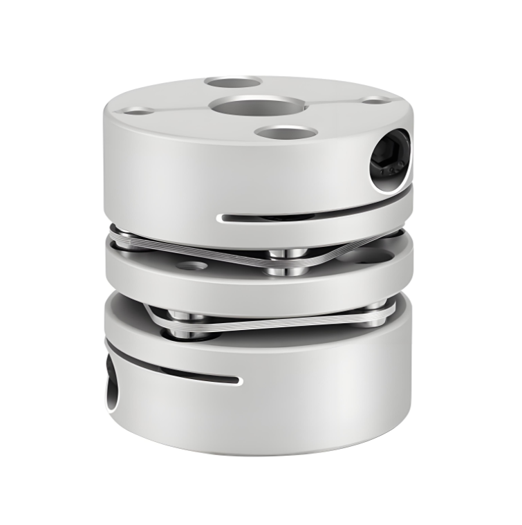 Алюминиевая муфта с двойной диафрагмой для сервопривода позиционирования с ЧПУ Эта короткая муфта зажимного типа с диафрагмами из нержавеющей стали обеспечивает высокую жесткость на кручение и низкую инерцию, что делает ее подходящей для точного управления сервоприводами и шаговыми двигателями в станках с ЧПУ. Посмотреть продукт →
 Высокая крутильная жесткость диафрагмы гарантирует, что муфта не создаст резонансный узел ниже рабочей скорости. Это критично для сервоприводов, которые за один машинный цикл проходят множество циклов скорости.
Морские и ударные системы
Суда и морское оборудование представляют собой отдельный набор условий: высокая вибрация, переменная скорость, частые ударные нагрузки и сложная атмосферная среда. Гибкий узел приводного вала с высокоэластичной муфтой поглощает как перекосы, так и крутильные вибрации, защищая коробку передач и подшипник карданного вала.
Этот тип муфты часто используется в морских силовых установках, поскольку он может компенсировать угловое смещение, которое естественным образом возникает при изгибе корпуса и изменении крутящего момента двигателя. Упругий элемент также изолирует линию передачи от вибрации первичного двигателя.
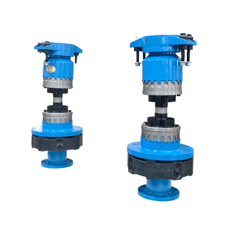 Гибкий вал в сборе для силовой установки морских яхт Эта антивибрационная система, разработанная для яхт, поглощает вибрации и перекосы трансмиссии, обеспечивая более плавное включение передач и защищая карданный вал от износа. Посмотреть продукт →
 Распространенные риски закупок и как их избежать
Определенные ошибки возникают снова и снова, когда инженеры и отделы закупок выбирают муфты из-за перекоса. Именно они приводят к ранним сбоям в эксплуатации или неожиданным простоям.
- Выбор муфты основан только на размере отверстия. . Совместимость отверстий ничего не говорит о том, имеет ли муфта угловую нагрузку, необходимую вашей машине. Всегда проверяйте степень смещения отдельно.
- Игнорирование коэффициента снижения скорости . Муфта, рассчитанная на угол 1,5 градуса при 1500 об/мин, может выдерживать только 0,8 градуса при 6000 об/мин. Проверьте кривую производительности производителя в зависимости от скорости.
- Учет влияния нескольких типов смещения . Когда угловое и параллельное смещение происходят одновременно, совокупное напряжение на гибком элементе выше, чем любое значение по отдельности. Используйте комбинированный расчет смещения из каталога производителя.
- Предположим, что необслуживаемая муфта не требует проверки. . Даже металлическая диафрагменная муфта имеет ограниченный усталостный ресурс. Установите интервал между проверками и следите за признаками износа кромок или растрескивания диска.
Практические рекомендации по обеспечению долгосрочной надежности
Некоторые эксплуатационные особенности могут значительно продлить срок службы муфты. Сначала затяните болты ступицы вала динамометрическим ключом до указанного значения и используйте фиксирующий состав там, где его рекомендует производитель. Ослабленная ступица вызывает истирание и быстро увеличивает отверстие вала.
Во-вторых, запишите значения выравнивания после установки и после первого запуска с полной нагрузкой. Небольшой сдвиг между этими двумя измерениями является ярким индикатором движения фундамента, теплового роста или структурного отклонения. Раннее обнаружение проблемы позволяет исправить состояние до того, как на муфте появятся видимые повреждения.
В-третьих, защищайте муфту от абразивной пыли, технологических жидкостей и сварочных брызг. Эластомерные элементы особенно чувствительны к маслу и теплу, а металлические зубья муфты предотвращают износ благодаря соответствующей смазке.
При перепроектировании привода или замене существующей муфты обратите внимание на физическое состояние старой детали. Асимметричный характер износа и изменение цвета являются информативными данными о неисправностях. Муфта, отполированная с одной стороны и шероховатая с другой, скорее всего, работала с неожиданной радиальной нагрузкой или чрезмерным параллельным смещением.
Размещение муфты в более крупной приводной системе
Соединения не следует рассматривать изолированно. Выбранный вами гибкий элемент взаимодействует с жесткостью системы вала и собственной частотой всей трансмиссии.
В приложениях с высокой крутильной жесткостью сочетание металлической муфты с точным стопорным узлом может помочь поддерживать точное угловое положение вала и ступицы. Запирающий узел создает эквивалент термоусадочной посадки за счет радиального расширения, что устраняет люфт шпоночного паза и обеспечивает концентричность, необходимую сервосистемам. Запорные узлы часто сочетаются с мембранными или сильфонными муфтами в блоках управления движением.
При установке в тяжелых условиях необходимо проверить муфту на крутильную вибрацию системы полного вала. Это особенно важно, когда зубчатая муфта подбирается для привода с длинным валом. Муфта с недостаточным демпфированием может усилить крутильный резонанс, даже если сама муфта рассчитана на крутящий момент правильно.
Итог для вашего приложения
Выбор гибкой муфты для компенсации несоосности сводится к нескольким твердым решениям. Определите значения крутящего момента, скорости и смещения, исходя из конструкции машины. Выберите семейство муфт, соответствующее этим значениям, и требуемый интервал технического обслуживания. Затем проверьте выбор на соответствие критериям снижения скорости и комбинированного несоосности, предоставленным производителем.
Для больших нагрузок и реверсивного момента наиболее долговечным вариантом является муфта барабан-шестерня. Для точного движения и высоких скоростей диафрагменная или сильфонная муфта обеспечивает необходимую жесткость. Для изоляции ударов и вибрации в морских или тяжелых промышленных условиях высокоэластичная муфта обеспечивает необходимые характеристики.
Когда сомневаешься, этот обзор барабанных зубчатых муфт для промышленных приводных систем Более подробно объясняется нагрузка и несоосность. Систематический подход к выбору муфты почти всегда предотвращает сбои в работе из-за несоосности, которые приводят к незапланированным простоям машины.


WeChat

WeChat

Whatsapp
Быстрые ссылки
Контактная информация

+86-511-85728317 / +86-511-85728316

+86-13861355442

sales@cnrsk.com (Сотрудничать)

№ 139, Цзиньян-роуд, промышленный парк Цзинган, район Цзинган, Чжэньцзян, Цзянсу, Китай.
Связаться с нами
Авторские права © Jiangsu Rokang Heavy Industry Technology Co., Ltd.
